PicoADC16 for Raspberry Pi Pico [W]
The PicoADC16 is a 16-port 10-bit ADC (Analog-to-digital converter) supporting up to 3.3 volts with screw terminals for easier usage.
The PicoADC16 is a 16-port ADC board with screw terminals using two 8-port MCP3008 10-bit Analogue to Digital converters connected to the Raspberry Pi Pico using a SPI interface.
The two MCP3008 ADC IC are banked A0-A7 (set chip enable "SPI CE A" low) and B0-B7 (set chip enable "SPI CE B" low). On each side of the board there are 10 screw terminals "GND, A0, A1, A2, A3, A4, A5, A6, A7, GND" and "GND, B0, B1, B2, B3, B4, B5, B6, B7, GND".
| Pico GPIO | Description |
|---|---|
| GP4 | SPI RX |
| GP3 | SPI TX |
| GP2 | SPI Clock |
| GP1 | SPI CE A |
| GP17 | SPI CE B |
The maximum input voltage for the ADC is 3.3 Volts.
Resistor Divider (for measuring voltages greater than 3.3 Volts)
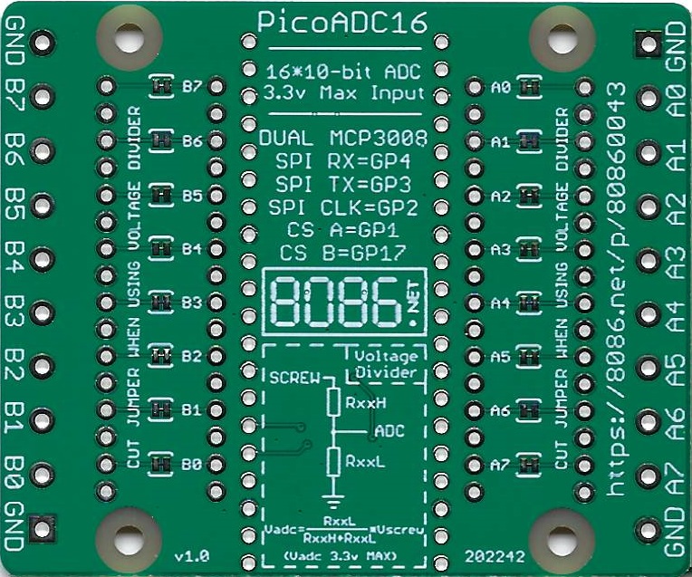
Each of the 16 ADC inputs has the option to use two through hole resistors (RxxL and RxxH) to create a voltage divider.
The formula to calculate the voltage at the ADC is "Vadc = RxxL / ( RxxH + RxxL ) * Vscrew". When using the voltage divider cut the appropriate solder jumper on the bottom of the board for that port (e.g. for port B4 you would populate resistors RB4H and RB4L and cut the B4 trace on the underside of the board).
For example to measure up to 60 volts you could use a 2.7k resistor for RxxH and 47K resistor for RxxL.
2700 / ( 2700 + 47000 ) * 60 = 3.25955 which is below the 3.3 Volt maximum input for the ADC.
NOTICE: After populating the resistors and cutting the solder jumper I strongly advise testing with a 3.3 Volt maximum input to ensure the solder jumper has been cut properly as connecting a high voltage to the input may damage the PicoADC16 and/or Pico.
Code Examples
CircuitPython
The example below requires the adafruit_mcp3xxx library is saved in the lib folder on the CIRCUITPY drive to work.
import busio
import digitalio
import board
import time
import adafruit_mcp3xxx.mcp3008 as MCP
from adafruit_mcp3xxx.analog_in import AnalogIn

# SPI bus
spi = busio.SPI(clock=board.GP2, MISO=board.GP4, MOSI=board.GP3)

# Voltage Multiplier
vdm = 3.3/65536

# Chip select pins
cs1 = digitalio.DigitalInOut(board.GP1)
cs2 = digitalio.DigitalInOut(board.GP17)

# create the mcp objects
mcp1 = MCP.MCP3008(spi, cs1)
mcp2 = MCP.MCP3008(spi, cs2)

adc_a = {}
adc_b = {}

# create analog input channels
adc_a[0] = AnalogIn(mcp1, MCP.P0)
adc_a[1] = AnalogIn(mcp1, MCP.P1)
adc_a[2] = AnalogIn(mcp1, MCP.P2)
adc_a[3] = AnalogIn(mcp1, MCP.P3)
adc_a[4] = AnalogIn(mcp1, MCP.P4)
adc_a[5] = AnalogIn(mcp1, MCP.P5)
adc_a[6] = AnalogIn(mcp1, MCP.P6)
adc_a[7] = AnalogIn(mcp1, MCP.P7)

adc_b[0] = AnalogIn(mcp2, MCP.P0)
adc_b[1] = AnalogIn(mcp2, MCP.P1)
adc_b[2] = AnalogIn(mcp2, MCP.P2)
adc_b[3] = AnalogIn(mcp2, MCP.P3)
adc_b[4] = AnalogIn(mcp2, MCP.P4)
adc_b[5] = AnalogIn(mcp2, MCP.P5)
adc_b[6] = AnalogIn(mcp2, MCP.P6)
adc_b[7] = AnalogIn(mcp2, MCP.P7)

test = digitalio.DigitalInOut(board.GP16)
test.direction = digitalio.Direction.OUTPUT

while 1:
	# Clear the screen
	print("\033[2J\033[H", end="")
	for i in adc_a:
		print('A'+str(i)+':', adc_a[i].value*vdm)
	print("")
	for i in adc_b:
		print('B'+str(i)+':', adc_b[i].value*vdm)
	test.value = not test.value
	time.sleep(0.3)